AR作为元宇宙入口,重要组成,也迎来发展史上的又一高光时刻。相比传统的电脑、手机,AR(Augmented Reality,增强现实)技术可以将2D或3D信息叠加到真实物体和现实环境中,革新了信息传递、显示、交互方式。在2022年开头,我们筛选复盘了2021年完结的十大工业典型应用案例,希望这些案例与经验,能给AR行业未来继续前行带来一些启示。
TOP1:钢铁行业——宝武钢铁打造AR智能运维系统,开启全新设备运维方式
在2020年,AR在钢铁行业的应用就可以说是初战告捷了。疫情期间,华菱湘钢的工程师通过亮风台提供的AR眼镜以及AR远程通讯与协作平台HiLeia的冻屏、实时标注等功能克服了疫情影响,与中德奥三地专家进行远程无障碍沟通协作,顺利实现跨国远程装配。这是我国钢铁业首次通过5G+AR进行跨国远程装配。在此后一年,华为即联合三大运营商、亮风台、宝武、华菱湘钢、河钢、柳钢、首钢等撰写发布了《5G智慧钢铁白皮书》,明确“5G AR远程装配”为5G智慧钢铁十大应用场景之一。
到2021年,宝武钢铁引入亮风台AR技术与应用,打造了“AR智能运维系统”,为冶金企业带来了全新的设备运维工作方式。
以往,在需要原厂专家远程协助、后端专业技术人员与现场点检人员信息交流、检修作业的多岗协同场景下,往往只能采用邮件、电话、微信等方式进行信息交换和沟通协作。基于当下信息化、智能化技术的飞速发展,以电子邮件、电话等方式传递信息、数据的效率已经不能满足高效、智能的工作需求,而使用微信等互联网即时通讯工具虽然一定程度解决信息传递效率的困扰,但同时又衍生了企业数据安全、信息碎片化等一系列问题。
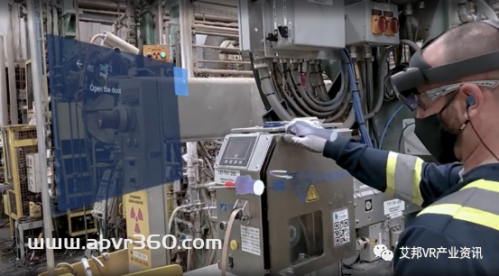
作为国内首批实现5G钢铁生产企业,宝武充分结合5G、云计算、边缘计算、大数据、人工智能、AR增强现实等新一代信息技术,借助与亮风台联合打造的AR智能运维系统,赋能运营维护、设备管理等各个环节,在发挥下沉式部署优势,保障数据安全的前提下,实现关联设备的数字信息可视化、精准远程协作与高效过程记录管理,最终完成基于“作业现场”的信息交互能力提升。
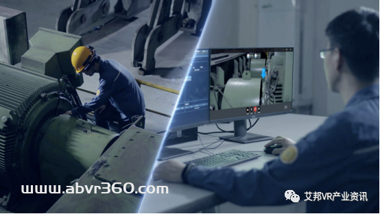
宝武现场运维人员佩戴亮风台最新5G AR智能眼镜进行设备运维工作
在2021年,基于早期的AR跨国装配经验,亮风台在钢铁行业开拓出了更丰富的应用场景,与钢铁行业实现了更精耕细作式的合作,进一步助力钢铁行业由“制造”向“智造”转型。
TOP2:能源行业——正泰集团,作业指导AR可视化,新手员工不犯难
熟练的“老师傅”宝贵又稀缺,面对复杂的电力设备、厚厚的作业指导书,现场的新手员工怎么办?2021年,正泰集团联合亮风台,引入AR利器,打造了一套“AR配电运维系统”。有了这套系统,上述一直困扰诸多能源企业的“紧箍咒”瞬间土崩瓦解。
“AR配电运维系统”,以可视化方式将作业指导书内容配置导入,现场新手员工佩戴AR眼镜,扫描设备二维码就能看到该设备的作业指导内容,按照提示进行一步步地规范操作。除了设备的图片、文字、PDF文件等,设备上的一个小按钮也能显示出对应的文字说明,极大提高人员现场作业规范水平以及工作效率。新手员工再也不用手忙脚乱的在现场翻阅厚厚的作业指导书,便捷高效的完成运维工作不再是难事儿。
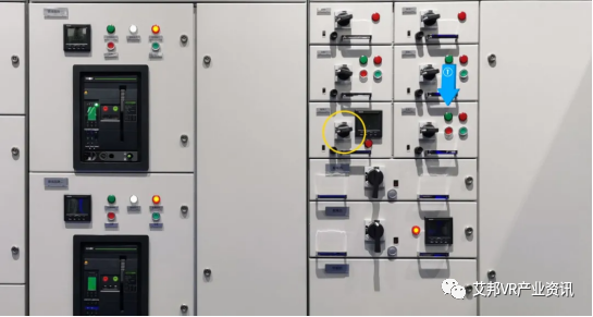
亮风台SLAM技术实现的精准3D标注效果
“AR配电运维系统”还可通过唤醒AR远程通讯与协作平台HiLeia开启多方远程会诊。后台专家可以在AR眼镜传回的第一视角画面上使用3D标注功能可视化指导现场人员完成相关操作或者是故障处理。值得一提的是,3D标注基于亮风台SLAM技术,它的特点就是精度高、速度快、支持各种复杂场景。在工业场景中,精准性很重要,否则一个小小的A按钮的说明被标记到B按钮去,造成操作失误将会带来难以预计的损失。
TOP3:自动化行业——罗克韦尔应用AR技术,创造性打破培训测试僵局
为了使员工保持和不断提升工作能力,企业常常会花费很大人力物力进行持续的员工培训。那么,面对复杂的技能知识,如何衡量员工确实掌握和理解到位?如何客观评估培训是否有效,在源头提升质量控制能力和交付能力呢?罗克韦尔自动化使用FactoryTalk InnovationSuite的AR功能找到了解决方案。
开发团队在Vuforia Studio系统平台构建了测试场景,引入了培训测试所需的CAD文件,以便创建映射到不同产品布局和接线示意的布线图。在Vuforia Studio系统平台,受训人员利用便携的平板电脑、手机或AR眼镜即可接受高度拟真的互动演示、培训。他们可以借助平台解决一些基本问题来证明他们确实理解了接线图,比如应该用什么颜色、什么尺寸、什么材质的线来完成接线图所要求的线路连接。系统可以提示多种可能的方式来帮助培训人员理解和完成测试过程。
通过这个系统,受训人员可随时随地进行测试,并且系统会记录下整个过程来帮助管理者分析、精确定位知识差距并通过进一步培训解决这些差距,提升员工能力。借助AR技术,罗克韦尔自动化最终实现了5%的培训时间减少,并将相同的培训方法扩展应用到了其他生产线。
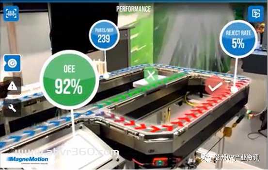
Vuforia Studio系统展示的虚实融合演示效果
TOP4:石化行业——东北石油局集成AR技术,打造存量系统融合新技术范本
对于很多工业企业来说,工业4.0转型升级过程中,虽然智能化得到了升级,但也伴随着系统越来越多,数据越来越海量的新问题,反而加剧了工作负荷,那么如何既能利用AR新技术来降本增效,又能不增加多系统负担呢?东北石油局在2021年打造了融合范本,实现了存量系统和AR新技术之间的断层弥合。
东北石油局在已有GIS平台基础上,集成亮风台AR远程通讯与协作插件HiLeia.PS,打造了“AR可视化协作管理平台”。该平台主要应用于故障诊断和应急维修两个场景,帮助后端专家与现场作业人员进行第一视角的可视化沟通。

现场工人点击地图标签即可呼叫远程支持,且系统支持GPS定位回传
很多时候,现场的问题只是一些小问题,但由于现场人员缺乏特定技能,很难在现场解决,故而浪费了大量的专家资源。另外有些情况是,专家到达现场,诊断出问题,但现场又缺少维修配件。由于配件运输时间长,专家只好先回去,等配件到了,再第二次奔波到现场解决。
宝贵的专家资源被大量浪费在路上,实属可惜。有了这套系统以后,三百多公里外的松原油田工人只要佩戴亮风台AR眼镜HiAR G200,就能马上得到长春石油局技术专家“如临现场”般的支持了。故而,借助这套系统,东北石油局有效释放了专家资源,极大降低了差旅成本,实现石油行业降本增效再进一步。
TOP5:重工机械——AR改变传统检修模式,打造低成本提升客户满意度范式
对于制造企业而言,时间就是金钱。如何缩短检修时间、提升检修效率,是制造企业在不断思考的问题。
2021年,韩国某跨国集团、全球重工机械制造商50强与亮风台合作打造的“远程智能巡检AR系统”上线。这套系统配合AR眼镜使用,可实现AR设备自动监测+专家远程支援两大功能,适用于各类工程设备巡检及维修工作,能够在故障、维修现场,通过远程技术支援,快速判断故障原因,拿出最效率的解决方案。
比如,如果设备确定需要到场处理,支援人员可提前了解现场设备情况,依据设备的运行状态和故障原因,提前准备好所需要的各类配件。这种方式规避了支援人员先奔赴现场检查,再回来等待维修配件到位的问题,极大提高了客户响应和服务效率。

巡检人员佩戴AR眼镜完成智能自检
工程机械属于重要的生产资料,在很大程度上有着不可替代性,一旦机器出现故障就意味着被迫停工,可能给客户造成严重的经济损失,甚至可能影响整个工程的进度。借助该系统,该跨国集团既节省检测时间,提高检测效率;也提高服务力量薄弱地区的维修服务效率;还可以减少装备停机时间、降低客户经济损失。一举多得,提升了客户满意度。
TOP6:汽车行业——上汽通用“AR智能车书”,用户买后体验再升级
在过去,第一次买车后,很多消费者会拿着厚厚的使用说明书,在自己的爱车上边翻边找边操作研究,这个按钮是什么意思、怎么设定巡航减速、碰撞系统怎么用……一系列的问题让人抓耳挠腮,厚厚的说明书既难懂又容易遗忘,最终只能躺在不知道什么地方默默吃灰。
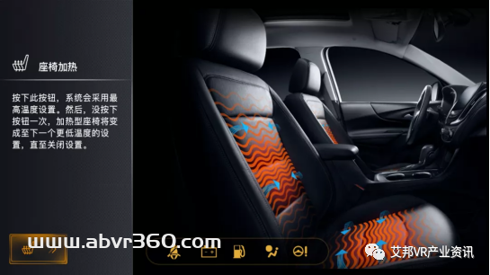
《雪佛兰AR车辆手册》演示“座椅加热”功能
2021年,亮风台与上汽通用合作,基于AI深度学习、AR等技术,打造《雪佛兰AR车辆手册》,借助该AR车辆手册,用户只需要通过手机扫描车内图标,就可以显示其对应功能、功能描述、动画演示、视频介绍等,包括识别错误提醒机制,帮助用户快速熟练新车、升温车人熟悉感。AR实时交互,能够真正有效减少用户使用负担,帮助轻轻松松了解新车的每一处细节,实现“一扫就知”!有了这套AR智能车书以后,广大车友们再也不用怕看不懂说明书了。
在技术层面,相比前两次亮风台与上汽通用的合作,双方本次合作的“雪佛兰AR车辆手册”做了重大技术升级,其基于训练卷积神经网络的深度学习技术,在进行AR车辆识别时,可以不断使用标注信息进行监督训练,使用轻量级模型框架加快前向推理速度,并且利用增强数据方法减小过拟合加强泛化能力。
TOP7:纸制品行业——Kruger“AR在职指导”,帮助员工应对信息化挑战
全球工业信息化和智能化发展浪潮下,工业作业现场的设备越来越复杂、要掌握的信息也越来越多,对于一线员工形成了巨大的挑战。为了提升员工面对复杂设备和海量信息的信心和能力,北美纸制品生产企业Kruger引入了AR技术,为员工在作业现场提供“在职指导”,提升他们的工作信心以积极应对信息化挑战。
Kruger工厂的员工正在“AR在职指导”帮助下进行设备操作
“AR在职指导”系统集成Power App和Dynamics 365 Supply Chain Management,在工作现场创建工作清单与步骤说明的数字信息。现场员工在工作时佩戴AR眼镜即可快速访问这些数字信息,触手可及。根据指示进行操作时,也不必担心自己的操作步骤有误而增加大量的检查和确认时间,极大提升质量控制与交付能力。
AR技术,为Kruger的一线员工提供了全新的学习与工作方式。
TOP8:家电行业——海尔AR应用再深入,开拓“首样质检”新场景
工厂首件产品检测对生产质量把控意义重大,如能及时发现首件产品问题就能够极大避免整体产线的产品质量问题,为企业规避损失。目前很多工厂采用人工检查并填报纸质单据的方式,检查过程用人多、效率低;报告及数据上传存在滞后、易出错、易遗漏等问题。
2021年,青岛中德智慧园区内的滚筒互联工厂引入亮风台AR智能眼镜和AR首件质检系统。质检员开始质检后,AR眼镜将自动开启全程录像。通过AR眼镜,质检员可以在检测现场查看到流程中每一步骤的检验内容、操作指导等数字信息、还可通过语音进行程序控制、质检项目选择、检测结果输入等。在完成整个场景后,将检验信息上传到质检后台,后台支持相关数据的查询、展示及报告的生成。AR首件质检实现了工厂工单无纸化、信息标准化、巡检电子化、管理可追溯等能力积累,助力海尔在首件质检中效率提升。
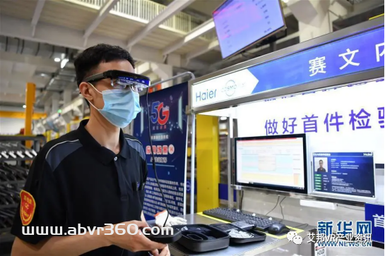
质检员演示AR首件质检过程
亮风台与海尔的合作其实由来已久。2019年5月开始,海尔智研院与亮风台达成战略合作,由海尔智研院牵头,共同成立国内首个面向工业领域的虚拟现实技术应用联合实验室。依托该实验室,双方在智能制造多个环节展开了密切合作,不断探索新技术应用场景,共同推动AR技术在海尔、海尔生态伙伴体系等工业场景中的商业落地。
TOP9:工程机械——三一集团以AR驱动服务升级,打通数字化服务“最后一公里”
传统客户服务模式下,服务工程师需要反复奔赴现场,花费大量时间清除故障;而服务工程师还会因为经验不足,需向异地专家寻求技术支持,而异地专家又“看不到说不明”。现场的不可视直接导致双方往往“鸡同鸭讲”,难以高效排故。
为此,三一集团引入亮风台,与树根互联融合,搭建售后远程支持平台,将AR技术应用于服务体系,与实时音视频、4G/5G无线通讯等技术相融合,为处于不同地点的一线现场人员和服务中心专家、售后团队成员建立一体化的AR协作空间,搭建售后服务体系故障解决、产品改进与培训的数字化赋能平台。

AR实时音视频协作效果图示
未来,三一工程师遇到难以解决的故障时,借助亮风台AR技术,利用AR扫描,即可智能识别故障部位,实时检索相关案例,并将现场“第一视角”情况传输至后方,由专家指导排故,即时判定故障责任,提高服务工作效率。
TOP10:食品饮料——百事可乐引入AR设备,提供跨越语言障碍的技能培训与生产效率提升
在没有引入AR技术之前,百事可乐位于南非德班的Prospecton工厂需要员工掌握四种以上的语言才能保证工作的顺利进行,这对普通一线员工来说几乎是不可能的。然而,通过在日常培训中引用AR技术,多国语言已经不再成为工作障碍了,只要佩戴上AR眼镜,不具备外语能力的当地工人,就可以在车间接受培训和开展工作。
与此同时,借助AR眼镜内置的视频会议软件Zoom,各地工厂及团队可以随时沟通,互相学习先进技术,交流经验。在疫情影响严重的百事爱尔兰工厂,管理人员需要在减少厂内操作人员数量的同时维持工厂的正常运转。他们借助AR眼镜内置的Zoom应用,就可实现居家办公人员与现场人员远程沟通,让工人可以便捷开展工作交流,最终提升生产效率。
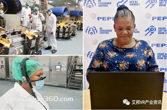
百事工厂员工佩戴AR设备进行工作
看完上述十大案例,我们不难发现,它们都跟一个词紧密相关,那就是“现场”。在2021年,AR远程协作实现连接现场与后端,已然成为工业界基础性标配应用。而更令人欣喜的是“可视化数字工厂”、“可视化作业现场”在不断得到发展和深化,AR在工业领域的应用在向更深层次发展!我们或可从中窥见一种未来在被更快、更广泛地实现,那就是AR连接的“可见”物理世界与“不可见”数字世界虚实融合的世界。
从VR/AR以及区块链、数字货币等新生事物始露苗头,5G商用落地,对下一代互联网的描绘一直不断,有人称为超级互联网、3D互联网、全真互联网、空间互联网,再到如今热议的“Metaverse(元宇宙)”。那2022年后的未来世界,究竟应该由谁来描绘和实现呢?我们或可朴素些表达,就是“下一代互联网”。
来源/制造界(ID:baixiu01)
作者/梁风


